The Control Board
Up until now I’ve focused on the display boards. These boards need something to drive them via i2c. At this point, the displays are being driven from an Arduino Uno/Breadboard.
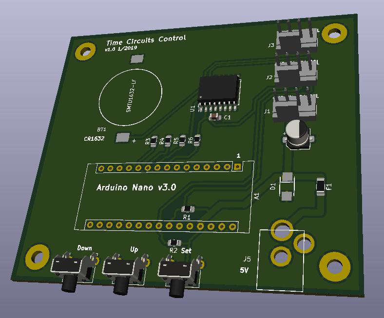
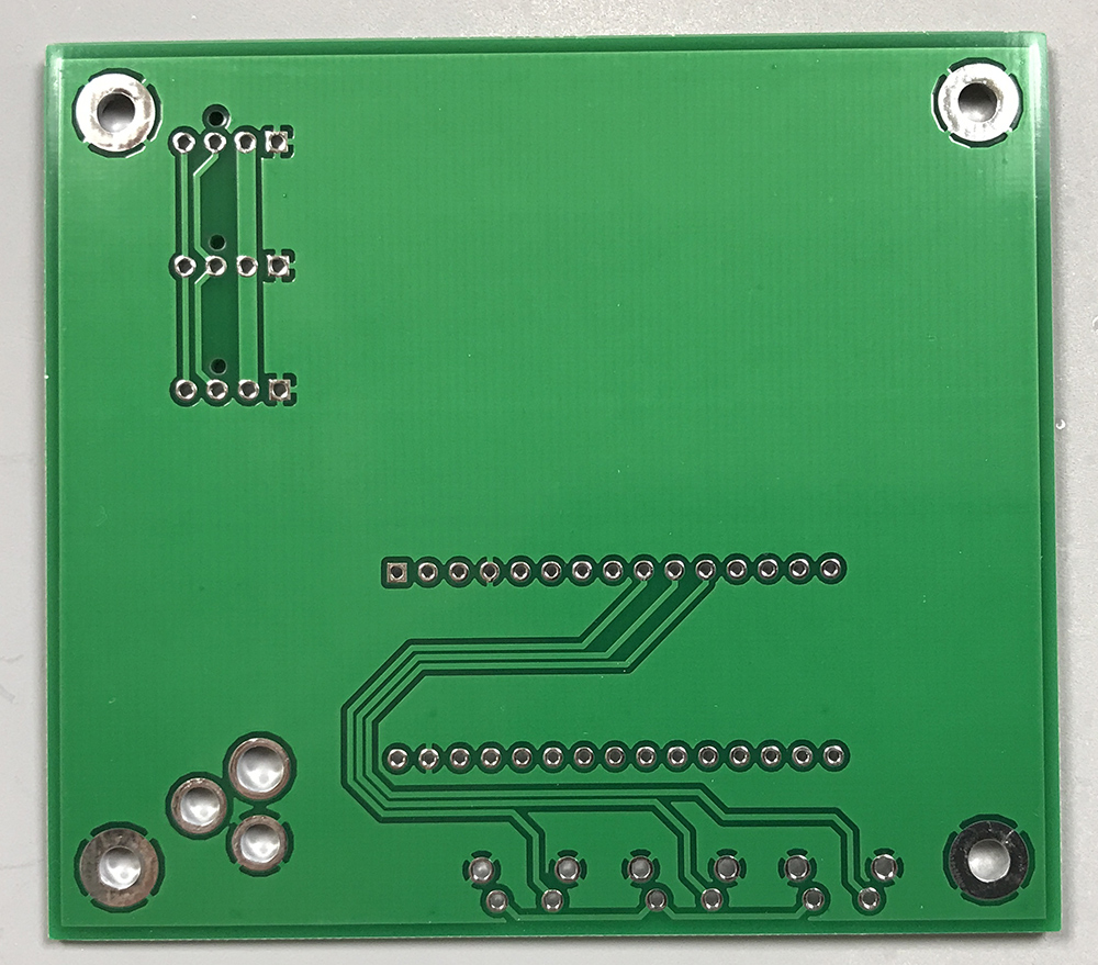
The initial goal was to create a custom board with the real time clock, buttons, power connector, connectors for the displays and a socket for an Arduino Nano.
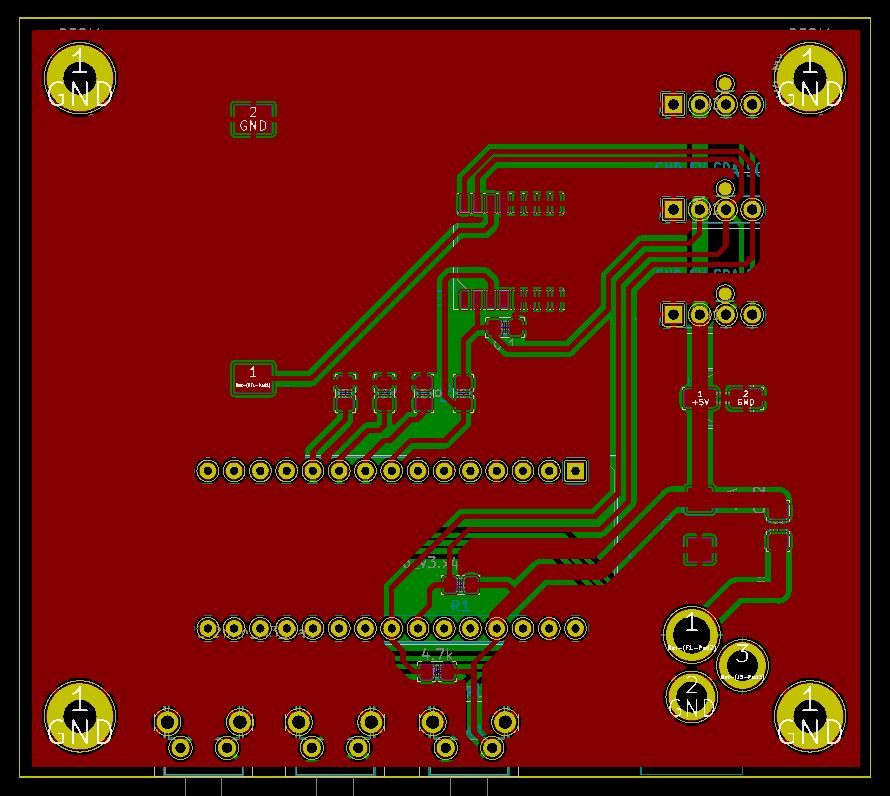
This board is much simpler than the display board and lay out only took about 3 hours.
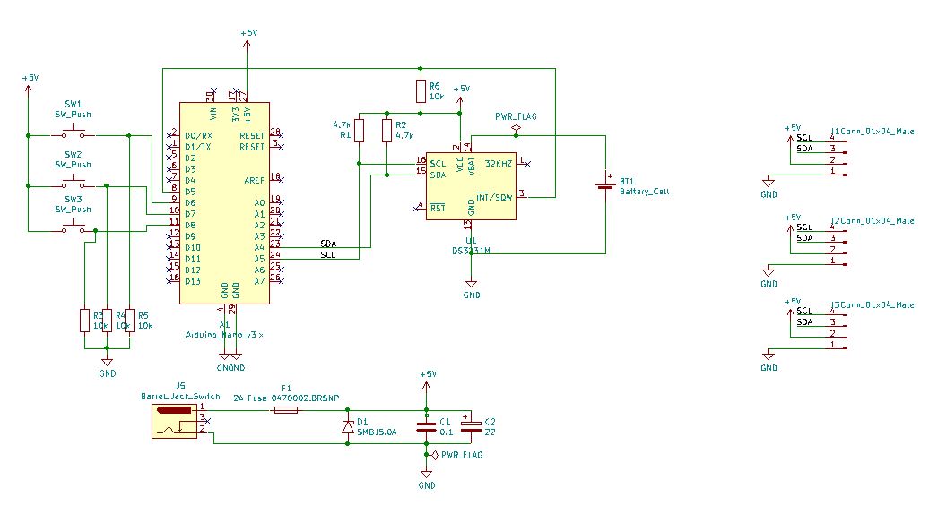
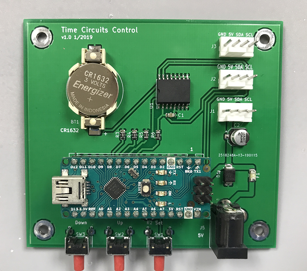
4 I/O pins on the Arduino Nano are used as inputs, 3 for buttons, and 1 to monitor the 1Hz output of the RTC. The buttons are used for setting the time and other configuration settings. The 1Hz RTC output is used for accurate colon blinking, not for determining the time. Time is retrieved from the RTC via I2C. Information to be displayed is sent to the display boards via I2C. Fusing and over/reverse voltage protection is also included.
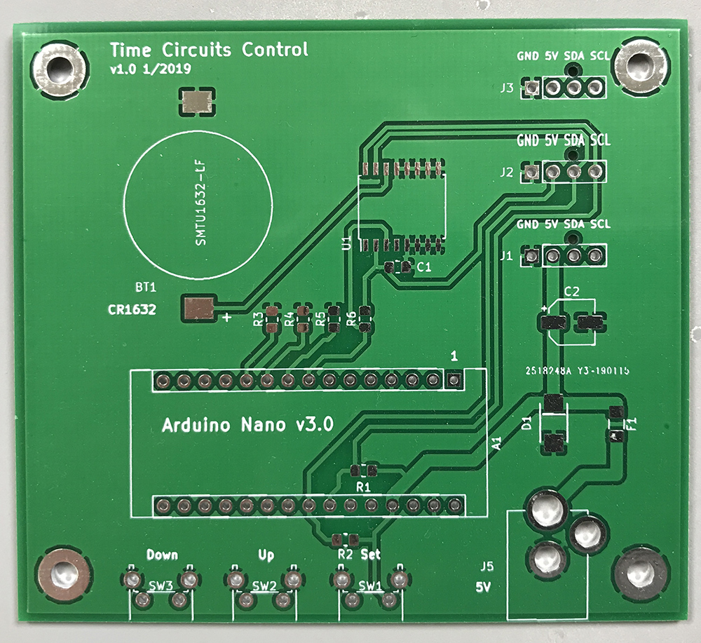
These boards were then manufactured by JLCPCB. This time the board were only $2 for 10 of them. With shipping, the total was $19.95. Again, they were quickly manufactured and arrived 6 days later.
Power
The Arduino and LED driver needs 5V. At this point the current needed wasn’t determined, estimated under 2A. So a suitable 5V power supply would be needed.
One option is to implement a voltage regular on the main board that would accept a range of voltages, like 9-12V.
The other option is to use an external 5V plug-in type power supply. This is the option I went went. The main reason is for simplicity, an onboard regulator would add some complexity as it would have to be of the buck type to keep heat down. A linear regulator at the needed current would produce too much heat. There’s also concern that any heat could interfere with the clock accuracy (even though a temperature compensated clock is used).
Advantages
- Simple to implement
- Using an external 5V power supply should in theory extend the clocks life since the power supply is the most likely to fail component and an external one can be easily replaced.
Disadvantages
- 5V will limit the cord length, if there was an internal regulator, higher voltages would mean less voltage drop and would be tolerant of the resulting lower voltage.
- 5V plug-in power supplies are less common. There’s a risk that someone may plug in a 12V power supply and cause damage.
A 2A fuse protects the circuit from catastrophic failure. The circuit is protected against excessive voltage (incorrect power adapter plugged in) a Littlefuse SMBJ5.0A transient voltage suppression diode is placed across the power supply. This device will short if the voltage exceeds 6.4V or is connected backwards. This should blow the fuse or cause the external power supply to automatically shut down and protect the circuit. The SMBJ5.0A is used for protection in the Raspberry Pi 3 B+.
The final design draws about 1.1A with all LED segments driven, the voltage drop is minimal and not a problem.
Real Time Clock
Since this is clock, it will need an accurate source for time. There are RTC clock chips available. I wanted to use one that used I2C and have a battery backup. One option is the DS1307. I’ve used the DS1307 before, it has battery backed time, uses I2C and is well supported by Arduino libraries.
Another require though is high accuracy. Over time these clocsk will drift. The DS3231 has an integrated crystal oscillator that is temperature compensated – it monitors the temperature and uses trimmer capacitors to compensate for any change in the crystal’s frequency. Since the crystal is integrated into the chip, this also makes design and assembly a little easier. This comes at a price, this chip is about $8.
So far, after several weeks of test, being powers and running from battery, the DS3231 seems to perform well and there’s no significant drift.
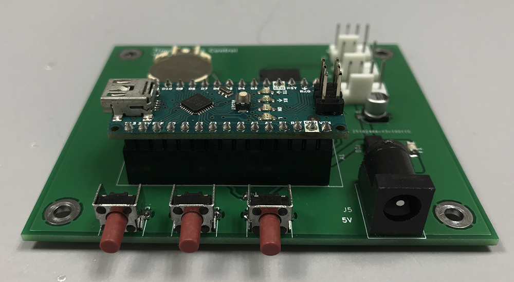
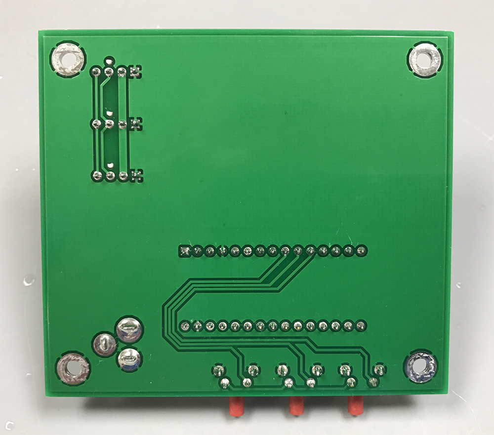
Testing the Control Board
The control board was assembled and worked as expected without any trouble. Again it’s a relatively simple design, there’s not much to go wrong, and luckily, nothing did. This version of the board has traces under the DS3231 RTC, the datasheet says this should be avoided. This has been corrected in the next version of the board. This doesn’t seem to cause a problem.
Awesome work dude