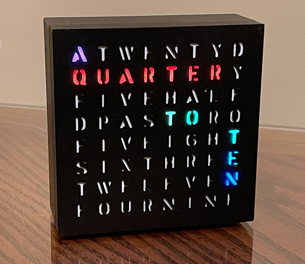
A 3d printed word clock.
A 3d printed version of the Adafruit NeoMatrix 8×8 Word Clock.
The 3D printer files can be found at Thingiverse here.
Features:
- Time Displayed as Words on Display
- High Accuracy Battery Backed Real Time Clock
- Programmed with Arduino IDE
- Custom PCB
- Easy Setting of Time and Brightness Settings
Case
The 3d printed case can be found here. I’ve modified it to remove the notch for programming, but that can be left if desired. An appropriate right angel header will be needed if it is desired to program it while assembled. I’ve also modified the defuses to be thinner to allow more light and recess the LEDs to reduce light bleed.
The case was printed with PETG. To smooth the sides and front, where necessary, Bondo Glazing and Spot Putty was used and sanded with 400 sand paper. Once smooth, it was painted with several coats of flat black spray paint. 3M Bumpon SJ5382 adhesive feet were used on the bottom. 4 1″ 4-40 machine screws attach the front to the back of the case. The screws will tap the holes when first screwed in. Care should be taken to not over-tighten the screws. 4 small salvaged sheet metal screws were used to mount the PCB. These screws measured 3mm in diameter and the threaded part measured 6.3mm.
Hardware Modifications
This implementation differs from the original Adafruit and Thingiverse versions in that it uses a custom PCB and high accuracy i2c real time clock.
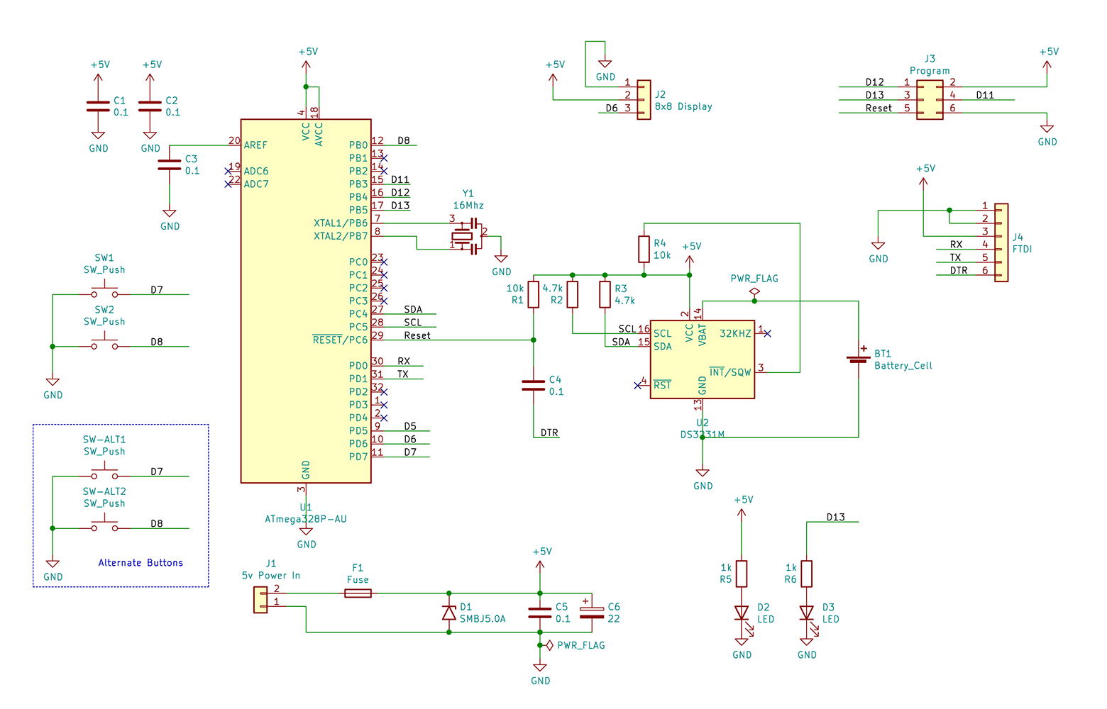
Schematic
Below is the schematic for the clock. It is essentially a 5V Arduino Pro MINI with DS3231 clock and related components. PDF link.
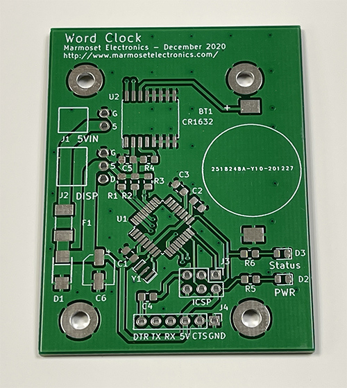
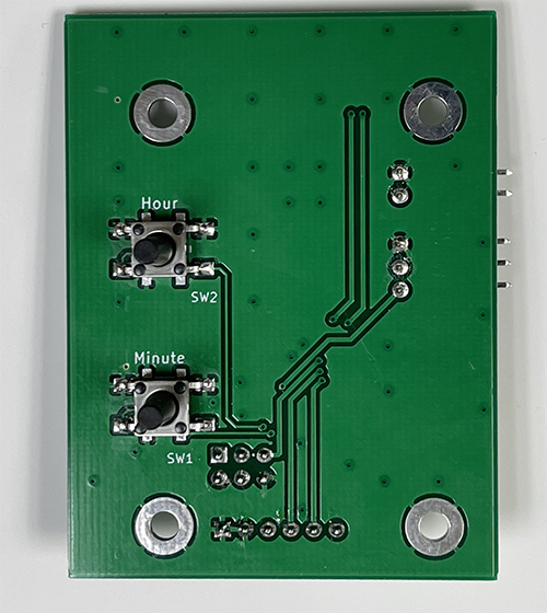
PCB
A custom PCB was designed to fit the existing 3d printed Thiniverse enclosure using KiCad. The initial goal was to not make any changes to the enclosure. Measurements were taken to insure the buttons and mounting holes would line up. The board is essentially a 5V Arduino Pro Mini with RTC, buttons and everything needed to drive the display. Using a PCB is a bit more work, but makes assembling additional clocks easy and gives a professional result.
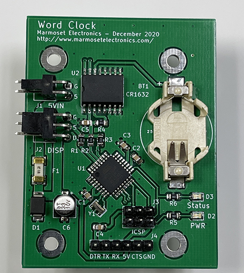
Assembly
Most of the surface mount components were soldering using solder paste and hot air. The battery holder and LEDs were soldered with a soldering iron to prevent damage melting the plastic in these parts.
Connections between the power jack and display were made using 22awg wire and Molex KK connectors. See parts list below for exact part’s used. These connectors are inexpensive and give a professional result, but require a relatively expensive crimping tool. Optionally the connectors may be omitted and the wires soldered directly.
The Adafruit 8×8 NeoPixel matrix is attached to the front panel using hot melt glue.
Setting Buttons
There are multiple options for the setting buttons. Provisions are made for two styles of tactile switches. 6x6mm surface mount tactile switches can be used with either short or long shaft. Alternately, mirominiature tactile switches can be used. If using a switch with a short shaft or the microminiature switches, a 3d printed button will be needed to activate the switches. The 3d printed buttons from the origional Thingivers design should work with 6x6mm switches. In this build, switches with long shafts were used.
Programming
An ICSP header is provided to load the Arduino bootloader or program directly. See here for how to use an Arduino as a programmer to load the bootloader. The example where the Arduino NANO should be used and the board type was also set to Arduino NANO.
Once the bootloader is installed. Use an 5V/TTL serial interface cable to connect to computer and treat it as an Arduino NANO. Example cable here.
Alternately, programs can be loaded without the bootloader via ISCP using the Upload Using Programmer option.
Code Modifications
The original Adafruit Word Clock provides no way to set the clock once the code is compiled. It sets the clock to whatever time it was when the code was compiled. So to set the clock, the code must be recompiled and loaded each time the time needs to be updated. It’s unclear why no method was provided to set the time.
The 3D printed Thingiverse version does provide 2 buttons for setting hours and minutes. The method used to set the time with this implementation is to add 60 seconds to the time to advance the minute and 3600 to advance the hour. This method is ok for hours, but for minutes, it places the time somewhere in the middle of the next minute – it doesn’t reset the seconds for the minutes in the RTC. The actual time is also not displayed while setting.
To improve setting, way to display the time precisely was needed while setting the time. To achieve this, the exact time is shown by using the first 2 rows on the display to indicate the hours. The number of letters lit is the hours. These are grouped in to 3 groups of 4 to make counting easier. An A on the third row indicates AM and is off for PM. The remaining bottom section of the clock displays the minute as 2 7-segment displays.
Pressing a button during normal operation enters set mode. The time is displayed as described above. The hour and minute may be adjusted via the corresponding button. Each time the minute is advanced, the second for the minute (not show, but stored in the RTC), is reset to 0. This allows for easy synchronization with a reference clock. Exiting setting mode is done by not pressing any buttons for several seconds.
The original code provides the option for reducing the brightness at night. This was originally hard-coded into the program. I decided to make these adjustable options as well. This was done by making a menu that cycles through setting the time, setting the night hours, and setting the brightness for night and day. Since there is no select or enter button, time (waiting) becomes the selection method. Select the desired option, wait, and it will be selected. The hours for night start/end are set in a similar way the hours for time is set with the number of letters lit corresponding to the time. The brightness is set in 8 steps using the display as bar graph to show the current brightness setting. With any of these options, once set, wait a few seconds to save and exist.
The settings for brightness and night hours are saved in the microcontroller’s eeprom and are recalled when powered up. Holding one while applying power until RESET appears will clear the saved settings. This causes the settings check sum to fail later in the program which results in default settings being loaded.
Pictures


Parts List
Part and Number (Mouser Part Number)
U1 – Microchip ATMEGA328P-AU (556-ATMEGA328P-AU)
U2 – Maxim integrated DS3231 DS3231S#T&R (700-DS3231S#T&R-)
Y1 – Murata 16MHz Resonator CSTNE16M0V530000R0 ( 81-CSTNE16M0V530000R )
C1, C2, C3, C4, C5 – 5x 0.1uF 25VDC 0805 Multilayer Ceramic (581-08053C104KAT4A )
C6 – 33uF 10VDC Nichicon UWX1A330MCL1GB (647-UWX1A330MCL1)
D1 – Littlefuse TVS Diode SMBJ5.0A (576-SMBJ5.0A)
F1 – Littlefuse 1A 451 Series Fuse 0451001.NRL (576-0451001.NRL)
D2 Green 0805 LED Lite-On LTST-C170GKT (859-LTST-C170GKT)
D1 Yellow 0805 LED Lite-On LTST-C170YKT (859-LTST-C170YKT)
SW1, SW2 – 2X Tactile Switches E-Switch 13mm TL3301DF160QG (612-TL3301DF160QG)
SW-ALT1, SW-ALT2 – 2x Alternate Tactile Switch C&K PTS525SM15SMTR2LFS ( 611-PTS525SM15SMTR2 )
R1, R4 – 2x 10k 0805 Resistor Vishay RCG080510K0JNEA (71-RCG080510K0JNEA)
R2, R3 – 2x 4.7k 0805 Resistor Vishay RCG08054K70JNEA (71-RCG08054K70JNEA)
R5, R6 – 2x 1k 0805 Resistor Vishay RCG08051K00JNEA (71-RCG08051K00JNEA)
BT1 – Renata Battery Holder SMTU1632-LF (614-SMTU1632-LF)
J1 – Molex 2 Pin Jack 171857-0002 (538-171857-0002)
J2 – Molex 3 Pin Jack 171857-0003 (538-171857-0003)
J3 – ISCP 6 pin .1″ header – 2 row X 3 pin
J4 – FTDI/Serial 6 pin .1″ header
10x Molex KK Crimp Terminals 08-51-0108 (538-08-51-0108-LP)
1x Molex 2P Housing 22-01-3027 (538-22-01-3027)
2x Molex 3P Housing 22-01-3037 (538-22-01-3037)
1x Panel Mount 2.1mm DC Barrel Jack Adafruit Prod ID 610 or equiv.
1x Adafruit NeoPixel 8×8 64 LED Pixel Matrix Prod ID 1487
1x 5V 1A Power Supply with 2.1mm plug
1x CR1632 Battery
22awg Red, Black, and White (or other color) wire for +5, Ground, and Display Data.
Files
3dfiles.zip – .stl files to print needed parts.
wordclock-arduino.zip – Arduino code
wordclock-pcb.zip – PCB gerber files for manufacture
Operating Instructions
Press any button to enter the settings menu. SET will be displayed, press any button within a few seconds to advance to the next option. Once the desired option is displayed, wait several seconds and that option will be selected. If an option is selected by mistake, press no button and simply wait several seconds and the clock will return to normal option.
The options are:
SET – Set the time
IGHT – Set the (BR)IGHT(NESS)
NH – Set the N(IGHT) H(HOURS)
END – Do nothing and exit
SET
This option sets the time.
The hours are displayed across the first two rows in blue. The number of letters lit represents the current hour. They are grouped in to 3 groups of 4 for easy counting. A yellow “A” appears on the third row to indicate AM and is not lit for PM. The minutes are displayed in green on the lower portion of the display as 7-segment display.
Press the Hour or Minute button to adjust the time. Holding the buttons will advance automatically. The minute restarts each time the minute is advanced. This can be used to synchronize the time with a reference clock. Once the time is set, wait several seconds and the clock will return to normal operation.
IGHT – (BR)IGHT(NESS)
This option sets the brightness.
The brightness for night, is shown on the left as a bar graph, the daytime brightness is on the right.
Press the Minute button to adjust the night brightness setting. Press the Hour button to adjust the day brightness. The display’s brightness will reflect the last setting change. Once maximum brightness is reached, another button press restarts the setting at minimum brightness. Once the brightness is set, wait several seconds and the clock will return to normal operation.
NH – N(IGHT) H(HOURS)
This option sets the N(IGHT) H(HOURS). This defines when night begins and ends. The display’s brightness will be set based on this time rage.
The hour is indicated by the number of letters lit. They are grouped in to 3 groups of 4 for easy counting. The start hour of night is shown on the left and end hour for night (beginning of day) on the right. Press the Minute button to adjust the start hour for night. Press the Hour button to adjust the end hour for night. An “A” next to the corresponding hours indicates AM and is not lit for PM. Once the times are set, wait several seconds and the clock will return to normal operation.
END
This option does nothing. It can be selected if an above option is selected by mistake. Once selected, wait several seconds and the clock will return to normal operation.
Clearing Settings
All options are saved and retained even if power is removed. Should the options need to be reset to the defaults. Disconnect power. Press and hold either hour or minute, re-apply power. Wait for the word RESET to be displayed. Release the button. Default settings will be loaded. The time is unaffected assuming the battery is OK.
Battery
A CR1632 keeps the real time clock running when power is lost or disconnected. Upon re-applying power the correct time will be displayed. If the battery was unable to maintain the time, SET will flash on the display when power is reapplied. Pressing hour or minute will go directly to time setting mode. Replace the battery and see above for time setting.