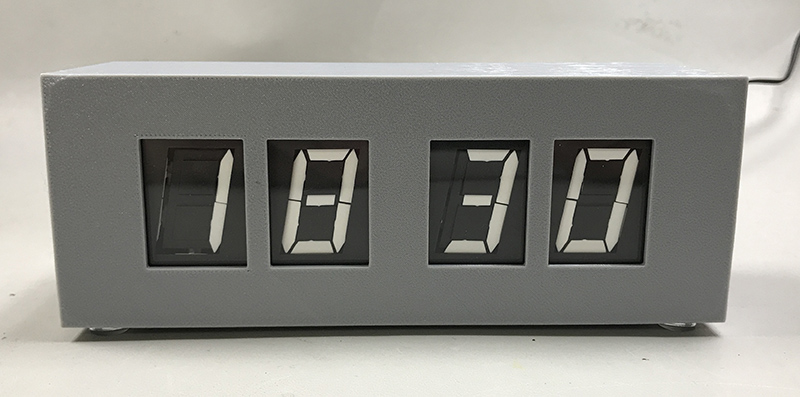
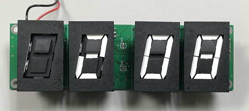
This is my build of Coyt Barringer’s flip display clock using Ferranti-Packard 1″ electromagnetical displays. These displays can be purchased on ebay. Info from the manufacturer can be found here. You can find a detailed circuit description, schematic, gerber files for the PCB and plans for a acrylic enclosure on his site. Details of my version are below and files for the 3D printed enclosure and parts list are at the bottom of this page.
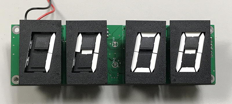
Each segment of the display is driven by an electromagnet. The segments have a magnet which is attracted or repelled by a electromagnet’s polarity. A 19V, 1ms pulse through the coil leaves it magnetized. An H-bridge is used to place the coil across the 19V supply with the desired polarity to set or clear the segment. To reduce complexity and parts, the displays are multiplexed, much as 7 segment LED displays often are. The polarity determines the direction of the magnetism and therefor sets or clears the corresponding segment.
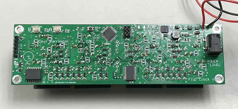
The displays are driven by what is essentially an Arduino Pro Mini, which runs at 8MHz at 3.3V. The Arduino boot loader was “burned” to the microcontroller (an Atemel 328p) to turn it in to an Arduino. After that, programs can be loaded directly via a serial connection (FTDI 3.3V) using the Arduino software.
The time of day is retrieved form a DS3231 realtime clock chip via i2c. A MCP23017 I/O expander is used for the needed number of outputs, also driven by i2c. The 19V is provided by a TI TPS61175 boost converter.
Assembly
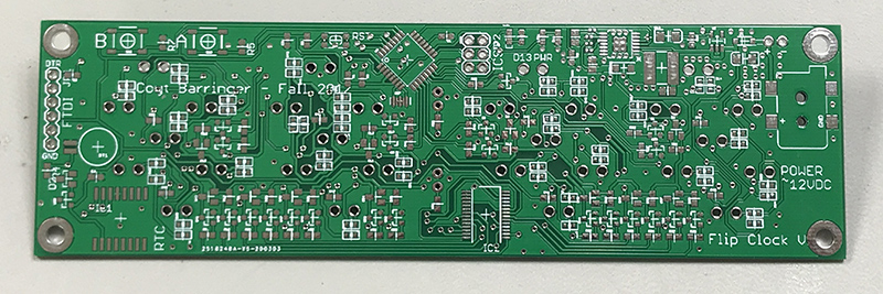
PCBs were ordered from JLCPCB using the gerber’s provided on Coyt’s web site. He used a different PCB manufacture, but JLCPCB read the files without a problem. The boards were received within 1 week of ordering.
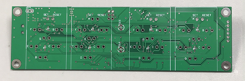
The board was assembled using hot air and syringe solder paste. Due to the large number of components, it was broken down in to sub-circuits that could be individually tested as it was assembled.
First the components that make up the Arduino Pro Mini were soldered. This includes the 328p microcontroller, 8MHz ceramic resonator, reset switch and pull up resistor, related capacitors, and headers for ISP and serial programming. Some some additional traces under ceramic resonator had to be cut to avoid shorts.
With these parts in place, it was time to test the Arduino functionality. An existing Arduino UNO was programed with the in circuit programmer sketch. It was then used to “burn” the bootloader on to the microcontroller, turning it in to an Arduino.
With the bootloader in place, loading a program via the FTDI serial interface worked as expected. A simple program to blink an LED at the D13 output was used – D13 is connected to an LED on the board and available via on an ISP pin. Note the bootloader was programmed with a 5V Arduino UNO, this is ok since the mircocontroler can operate at this voltage. Going forward it will be powered by the FTDI interface or the onboard 3.3V regulator.
With the microcotrller tested and working, I decided to build the 19V boost converter. The TPS61175 has a thermal pad on the bottom – a small amount of solder was applied to the pad on the board and flux added, with solder paste on the pin’s pads, hot air was used to heat the board and chip to affix the solder pad and pins. The resistors in this part of the circuit are small 0402 parts and are not labeled, so care must be taken to not mix them. There is also a very small 0201 capacitor. With the parts in place and the enable pulled high, 12V was applied and 18.8V appeared at the output, confirming operation.
Next the DS3231 real time clock and I/O expanded were added. At this point I haven’t ordered the battery yet, so the battery connections were shorted (datasheet says to connect battery input to ground when battery isn’t used). Resistor R4 was left unconnected so the charging circuit shorted. Next the clock program was loaded and modified to print the time via the serial connection for testing. The program was also modified to turn the display segments all on and off and the outputs of the I/O expanded were checked to verify it was sending the pulses expected to do this. The hour/minute set button pull-down resistors were also installed at this time, without these, erratic setting operations occur.
Finally it was time to complete assembly. A large number of mosfets, diodes and resistors must be soldered. This took the most time. Once completed the 3.3V regular and final power related parts were installed. 1 display was solder and ready for testing. Everything worked as expected with 1 display, so the remaining displayed were soldered in place. And… It worked!
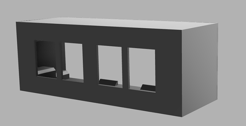
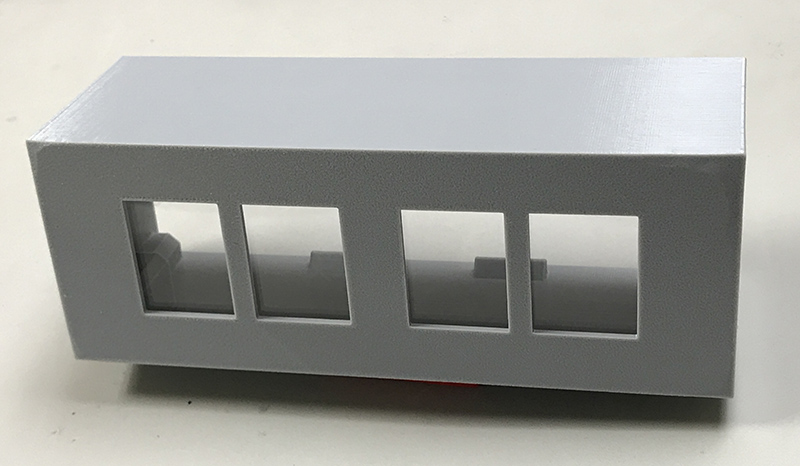
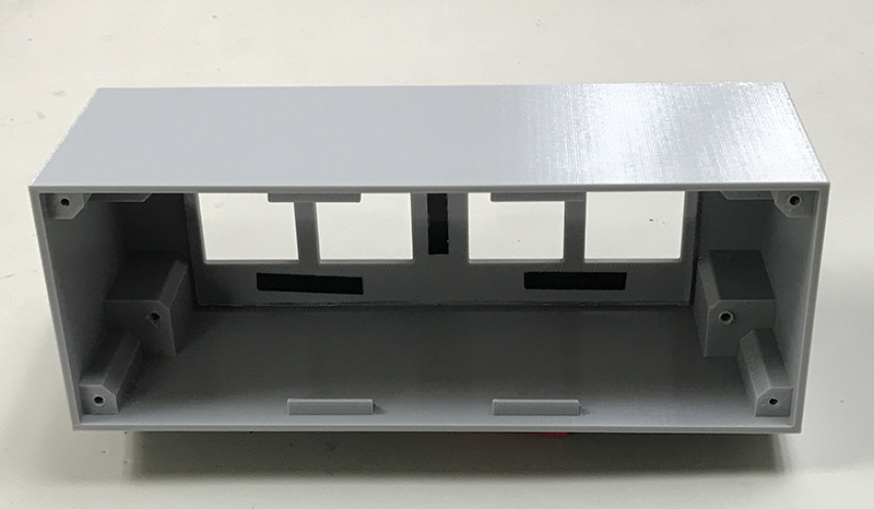
3D Printed Case
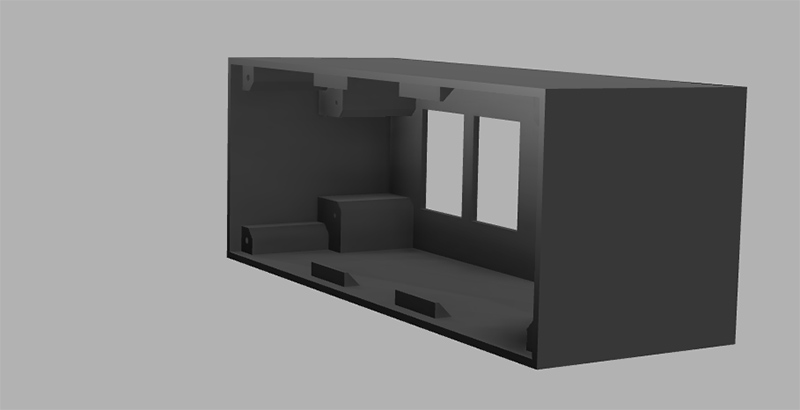
I decided to create a 3D printed case for the clock. It’s not too exciting, measurements were taken for the display windows, mounting and mounting for the board.
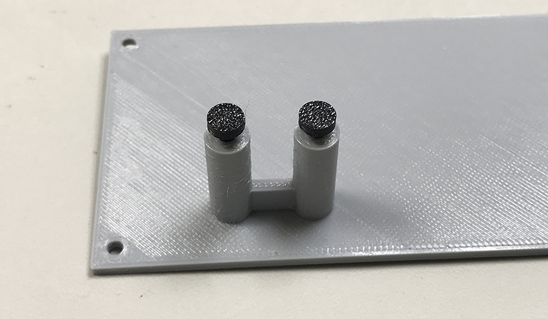
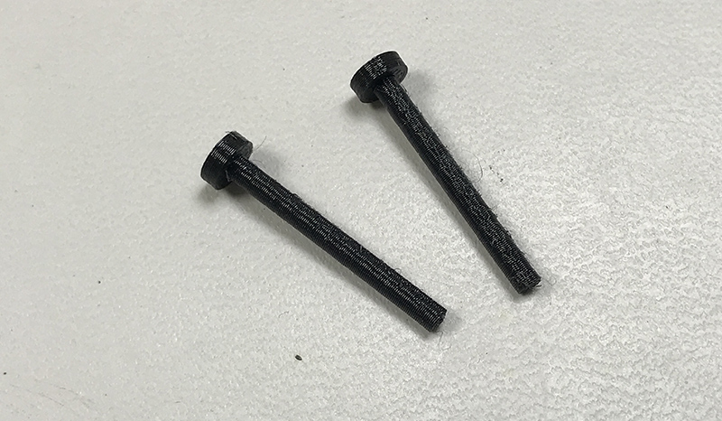
The time setting buttons are surface mount buttons on the board. I considered adding panel mount buttons, but decided to try a plunger type arrangement to extend the reach of the buttons to the back of the enclosure. Measurements were taken and a back panel with two tubes to hold the plungers was printed along with the plungers. The first set of plungers were about 1mm too long, they kept the buttons pressed. Shortening them gave very good results and reliable operation.
The way the power jack is mounted on the board will not work in this configuration. A panel mount jack will be needed for power. For now, the 12V power adapter wires will be connected directly to the board.
See assembly notes below for assembly.
The STL files to 3D print the enclosure can be found at the end of this document.
Software
The original designer of this clock also provided the code to run the clock. While the code may look complex at first, it’s not difficult to understand or work with. It’s simply reading the time from the real time clock (DS3231) via i2c and then use a switch/case statement to enable/disable the appropriate outputs to activate the display segments.
I did make some modifications to the code because I wanted to add and change some functionality. First it was modified to use the Adafruit RTClib library for interacting with the DS3231. This was done because I’ve used this library in the past and was familiar with it and this code appears to be actively maintained. The library originally used has not been updated in several years.
Next I wanted to add 24 hour support. The RTC library already provides the time in this format, so modifications to the code are trivia. However, I wanted the the option to switch between 12 and 24 hour mode. I decided to implement this by holding the hours setting button while powering on, if held for several seconds it switches from 12 to 24 or 24 to 12 and displays the new setting. This setting is stored in the 328P’s built in eeprom so the setting is remembered. The code simply checks if the hour set button his held when first powered up. If it is, the setting is changed and stored. If the button is not, the eeprom is simply read and the mode is applied based on its value.
Next I waned to modify the setting behavior. The clock is set by pressing the hour or minute button to advanced the corresponding value. The original design monitored the buttons with each pass through the main loop and incremented the value. This worked ok, but made setting the clock precisely difficult. The code was modified so that the value would increment once and stop. Continuing to hold the button more than 1 second will cause the time to begin incrementing quickly as long as the button is held. The time is set in the RTC immediately after the first increment. When pressing an holding, the time is stored upon release.
The way the minutes are set was also modified to set the seconds to 0 when setting the minute value. This was done to allow manual synchronizing with a reference clock. To synchronize, set minutes to the reference minute then press the minute button at the start of the next minute.
The clock also features white LEDs to illuminate the clock. This actually doesn’t work as the light cannot pass through the displays. These LEDs can be enabled/disabled via software, so the software was modified to not turn these on. The original code turned these on/off based on the time of day.
The D13 LED indicates AM/PM. This was set to come on for PM, however, it was set to come on when the hour is > 12. This was modified to >= 12, PM starts at 12, using > was causing it to come on at 1:00PM (13:00).
Finally the buttons were switched so that the hour setting button was on the hour side and the minute on the minute side.
Some Assembly Notes
The screws used for the back cover are #4 1/2″ sheet metal screws. The screws to mount the PCB were screws salvaged from something else. They measured 2.88mm in diameter by 8.3mm long. The same screws used on the back cover should work as well. The holes in the case for the PCB must be made slightly larger. A 2mm thick 57mm X 129mm clear piece of acrylic is inserted between the displays and the front panel to keep dust and dirt out. It is taped in place using double sided tape. A 12V DC 1A power adapter powers the clock. It’s connector was removed and wired directly to the PCB. Alternately a panel mount DC jack may be used which requires drilling the hole larger. The DC jack on the PCB is not in a position that can be used and is an odd size.
Resources
Another build by KainkaLabs on YouTube. He provides a BOM which was very helpful. However, the 0603 resistors are incorrect. The needed resistors are 0603 imperial. The part numbers in the BOM are for 0603 metric, which are 0201 imperial – way too small. Spreadsheet of the BOM is found in the zip file below. In some cases more items were ordered since it was cheaper to order more.
Information from the manufacturer of the displays can be found here. The datasheet for the displays can be found here.
PCBs – I have a few extra unpopulated PCBs available for the cost of mailing to US destinations only. If you intend to build this, request via the contact link at the top of this page. Request one only if you intend to follow through iwth it’s assembly since there are only a few available. Outside of the US it’s probably easier to just have the PCBs made in China and shipped to you.
My BOM, 3D printed parts and my Arduino code can be found in this zip file.
Additional info including schematic, gerber files for PCBs and even fully assembled boards (less displays) are available on Coyt Barringer’s web site.